VAREGA ENVICOM®
Gautschi | Markus Bauinger, Sales Manager
VAREGAENVICOM®
Advancing the energy efficiency and sustainability of melting technology.
Gautschi began to develop proprietary burner systems in 1958. By the 1990s, with its release of the VAREGA regenerative burner system, Gautschi was setting new standards for energy consumption when melting aluminum. To not only meet today’s demand for BAT (the “Best Available Technology”), but to surpass it by fulfilling the most stringent requirements for environmental impact mitigation, development of the burner product line continued, and it is now available as VAREGAENVICOM®.
REDUCED ENERGY CONSUMPTION / CARBON FOOTPRINT
VAREGAENVICOM® burners employ a regnerative thermal energy recovery system, which can preheat the combustion air up to a temperature of 1050 °C. When heating aluminum from 20 °C (solid) to 720 °C (liquid), this allows a specific energy consumption below 550 kWh per metric ton of aluminum to be achieved. Furthermore, the carbon footprint remains below 110 kgCO2eq per metric ton of molten aluminum.
REDUCED EMISSIONS
The high combustion air temperature theoretically allows an adiabatic flame temperature of 2272 °C. However, high flame temperatures can cause undesirable nitrogen oxides to form in the exhaust gas. To allow stricter emissions limits to be upheld, the burner head design was developed that significantly reduces the flame temperature. Two methods are used to achieve this:
- Staged combustion
The controlled distribution of the fuel/air mixture among multiple burner head zones allows targeted reduction of the flame temperature without affecting combustion efficiency. - Internal Flue Gas Recirculation (IFGR)
In the combustion chamber, part of the hot exhaust gas mixture is mixed with the combustion air. This reduces the oxygen concentration, further reducing the flame temperature.
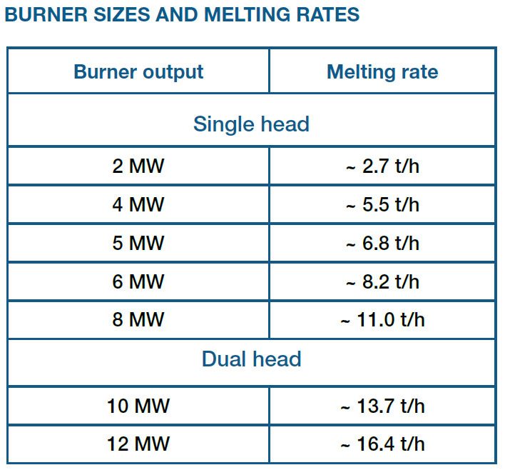
MEASURED VALUES
Under real-life conditions, the following average exhaust gas values were measured at a 35-ton Gautschi melting furnace (SVE-35) equipped with a 5 MW VAREGAENVICOM® heating system:
- NOx: ≤ 140 ppm
- CO: ≤ 44 ppm
- VOC/TOC: ≤ 5 mg/m³ at s.t.p.
THE ADVANTAGES
To increase operational safety, the positioning of the flame supervision system in the burner head has been optimized. The state-of-the-art burner control system incorporates high-quality measurement and control units for safety-relevant tasks that fully comply with EN 746-2 or comparable standards. Separate fans supply the pilot and main burners with cooling and combustion air, with the combustion air supply switching alternately between the burners. Measurement of the oxygen content in the furnace chamber allows precise control of the gas/air ratio, allowing a target oxygen content value of 2 % to be maintained in the furnace atmosphere. An exhaust gas fan creates the negative pressure required to draw exhaust gases out of the furnace chamber and through the regenerating material, while the pressure inside the furnace is regulated using a pressure control valve in the exhaust gas line. Continuous supervision of the process is possible, thanks to additional pressure and temperature measuring systems integrated directly into the burner. The full integration into the furnace control system allows all relevant operating data to be visualized in real time. This means that an overview of the process is available to the operators at any time.
MODULAR, EASY TO MAINTAIN, FLEXIBLE
The regenerators of the VAREGAENVICOM® system can be flexibly configured and can be equipped with ceramic balls or honeycomb bricks, whichever is best suited to their intended application.
- Honeycomb bricks:
Ideal in dusty conditions, such as those found in scrap recycling facilities. They are distinguished by the small pressure loss they allow and their long maintenance intervals. - Ceramic balls:
Have the advantage of allowing straightforward, rapid replacement of the storage material. They allow the volume of the regenerator to be reduced and the initial load of filling material is less expensive.
The system is also extremely flexible in terms of the arrangement of the regenerators. Depending on the space available and maintenance requirements, a choice can be made between two variants:
- Roof-mounted:
Allows easy, rapid access to the regenerator, without the need to remove bolts or release clamps. This is ideal for reducing the time required for maintenance. - Floor-mounted on rails:
Allows the use of high-volume regenerators, and can be removed for maintenance without the use of a crane. This variant is particularly advantageous when available space is very limited or in workshops with limited crane availability.